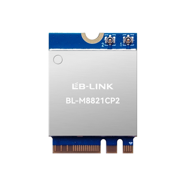
A high-power wireless module can help OEMs build robust video, telemetry, and control links where ordinary short-range connectivity is not enough. Yet transmit power alone does not create a dependable long-distance LoS transmission link. Antenna placement, receiver sensitivity, channel bandwidth, interference, thermal design, regulatory limits, and the quality of the ground-side system all affect the result. This guide explains how to evaluate a high-power wireless RF transmitter module for clear line-of-sight applications and turn a promising specification into a practical, testable wireless design.
Key Takeaways
A long-range RF link is a system: module power, receiver sensitivity, antennas, cable loss, bandwidth, installation, and environment all matter.
Clear line of sight improves propagation, but Fresnel-zone clearance is also important; an apparently unobstructed path may still perform poorly.
Narrower channels can improve link robustness when an application does not require maximum throughput.
A module’s advertised range is a design reference, not a universal field guarantee.
Thermal, power-supply, antenna, and compliance decisions should be made early in the product-development cycle.
What Makes a High-Power RF Module Different?
An RF module combines the radio, baseband processing, interfaces, and often the power-amplifier and low-noise receive stages required to create a wireless link. A high-power wireless module adds more transmit capability than a conventional embedded module, allowing the system designer to increase the available link margin when it is permitted and appropriate.
That margin is valuable in applications such as UAV video downlinks, temporary security cameras, robotic platforms, outdoor inspection systems, and point-to-point data links. In each case, the objective is not simply to send a stronger signal. It is to maintain a usable connection when distance, motion, interference, and installation constraints reduce the signal arriving at the receiver.
The first distinction to make is between transmit power and effective radiated performance. Conducted power is measured at the module’s RF port. The energy that actually leaves the antenna depends on antenna gain, feedline loss, connector quality, enclosure effects, and antenna orientation. On the receiving side, antenna gain and receiver sensitivity determine how little signal the system can still decode.
This is why two products using the same nominal high-power wireless RF transmitter module can perform very differently in the field. One may use matched antennas with clean cable routing and an unobstructed path; another may place antennas close to carbon fiber, motors, metalwork, or switching electronics. The module may be identical, but the radio system is not.
Why Long-Distance LoS Transmission Still Needs Engineering
“Line of sight” is often interpreted as a visible path between two endpoints. For RF design, that is only the starting point. A reliable long-distance LoS transmission path also needs adequate clearance around the direct path so radio energy can propagate without destructive reflections or diffraction from terrain, structures, vegetation, or moving equipment.
The practical implication is simple: raising one antenna by a small amount can sometimes improve a link more than increasing radio power. Antenna height, aiming accuracy, polarization, and ground-station location are design variables, not installation afterthoughts.
A second consideration is distance variation. A drone moving away from a ground station, a mobile robot passing behind equipment, or a camera mounted on a mast all experience changing path conditions. The link should therefore be designed around the weakest expected operating point rather than the best test result obtained at close range.
A third consideration is interference. The 5 GHz band can support high-throughput wireless applications, but the local RF environment may include other access points, wireless bridges, radar-related restrictions in some regions, and nearby electronic noise sources. Selecting a clear channel, using appropriate bandwidth, and validating performance at the deployment site are essential.
Start with a Link Budget, Not a Range Claim
A link budget turns a range objective into an engineering question. It accounts for transmit power, antenna gain, cable losses, propagation loss, receiver sensitivity, and a safety margin for real-world variation.
A simplified expression is:
Received power = Transmit power + Tx antenna gain − Tx losses − path loss + Rx antenna gain − Rx losses
The received power must remain above the receiver’s sensitivity threshold for the selected modulation, coding, and channel bandwidth. The difference between received power and that threshold is the link margin. More margin generally means greater tolerance to interference, rain, orientation changes, antenna mismatch, and installation variation.
Design factor
Why it matters for LoS range
Practical question
Transmit power
Increases the signal available to the link, subject to legal limits
Is the configured output appropriate for the market and antenna system?
Receiver sensitivity
Determines how weak a usable signal may be
What sensitivity applies at the required data rate and channel width?
Antenna gain
Focuses energy in a useful direction
Is the link point-to-point, mobile, or multi-directional?
Channel bandwidth
Affects throughput, noise floor, and robustness
Can the application operate with a narrower channel?
Cable and connector loss
Reduces RF energy before it reaches the antenna
Are cables short, correctly specified, and securely terminated?
Fade margin
Protects against changing real-world conditions
Has the system been tested beyond its minimum acceptable distance?
Site conditions
Affect reflections, blockage, and interference
Does the final installation match the test environment?
The table also shows why a high-power design should not be judged only by a dBm value. A lower-power module with a better antenna configuration and a cleaner channel can outperform a higher-power module installed poorly.
Selecting a High-Power Wireless Module for the Application
The right module depends on the data being sent, the mobility of each endpoint, the regulatory region, and the physical design of the host equipment.
For high-definition video, throughput and latency are central requirements. The radio link must carry encoded video with enough headroom to avoid frequent bitrate collapse. This often favors higher-throughput Wi-Fi architectures, multiple spatial streams where appropriate, effective antenna diversity, and careful channel planning.
For command, status, or low-rate telemetry, the design priorities may be different. A lower data rate, more robust modulation, and a frequency band better suited to the environment may deliver more dependable control coverage than a high-throughput link. It is important not to choose a video-oriented module simply because it advertises a large range figure.
For portable or airborne products, size, weight, heat, and input power must be considered alongside RF performance. A high-power front-end can increase the thermal load and demand a cleaner, more capable power supply. Engineers should plan the ground plane, heat-transfer path, regulator headroom, and shielding strategy before finalizing the enclosure.
A useful product-level reference is the BL-M8812EU2 2T2R Wi-Fi module. Its published specification identifies a 5 GHz, 2T2R design with USB interface, IEEE 802.11a/n/ac support, an integrated high-power FEM, and support for 10 MHz narrow-bandwidth operation. These attributes make it relevant when a compact Wi-Fi-based video or data link needs more design flexibility than a standard consumer-grade module.
Bandwidth Is a Range-and-Throughput Trade-Off
Channel width has a direct effect on system behavior. Wider channels can carry more data under favorable conditions, which is helpful for high-resolution video or multiple streams. However, wider channels also admit more noise and require a stronger signal to sustain the highest data rates.
When a mission requires dependable communication farther from the ground station, a narrower channel may be a more effective choice than simply seeking additional transmit power. It reduces the amount of spectrum used and can allow the radio to maintain a more resilient modulation-and-coding mode. The trade-off is lower maximum throughput.
This decision should start with the actual application data budget. Determine the encoded video bitrate, telemetry load, control traffic, packet overhead, retransmission allowance, and desired reserve capacity. Then select the lowest channel width and data-rate profile that can deliver the required user experience with meaningful link margin.
For example, an inspection drone sending one compressed video stream and low-rate telemetry may prioritize consistent picture quality and controllability over peak throughput. A temporary site camera with a fixed directional link may be able to use a higher-gain antenna and a carefully planned channel, enabling a different balance. There is no universal best configuration.
Antenna Design Has an Outsized Effect
Antenna selection should be made as part of the wireless architecture, not after the PCB has been completed. The antenna must match the operating frequency, fit the mechanical design, maintain a reasonable radiation pattern, and remain clear of RF-obstructive materials.
Directional antennas are often suitable for fixed point-to-point LoS links because they focus energy toward the intended endpoint. They can improve the link budget at both ends, but they require accurate alignment. Omnidirectional antennas are more suitable when one endpoint moves or the direction changes frequently, although their lower directional gain can reduce achievable margin.
Polarization is equally important. If one antenna is vertically polarized and the other is horizontal, the mismatch can severely weaken the connection. Installers should document polarization, orientation, connector torque, cable routing, and antenna position so a successful test configuration can be reproduced in production.
For UAVs and mobile robotics, antennas should also be evaluated across expected motion and orientation. A link that works with the platform on a bench may weaken dramatically when the airframe banks, rotates, or places battery packs and electronics between the antenna and the ground station.
Designing for Video, UAV, and Security Links
High-data-rate long-range designs commonly combine a camera or sensor, encoder, host processor, wireless module, ground receiver, display or control software, and antennas. Any one of these components can create a bottleneck.
For UAV video systems, the radio must coexist with flight-control electronics, motors, electronic speed controllers, GPS hardware, and other transmitters. The integration plan should include power filtering, physical separation between sensitive RF paths and noisy electronics, secure antenna mounting, and repeatable cable management. Bench testing should be followed by ground-range tests, then controlled flight tests that capture RSSI, packet loss, bitrate, latency, and video quality at different distances and orientations.
For security systems, endpoint placement is often fixed, so installers can benefit from directed antennas and deliberate site surveys. Trees, new buildings, seasonal foliage, and vehicles can alter a once-clear RF path. Building a margin into the design is more prudent than operating at the edge of a lab-measured limit.
LB-LINK publishes a long-range drone video transmission solution that lists several module options by interface, antenna support, bandwidth capability, and application-oriented distance guidance. Treat these distances as solution references under specific conditions, then validate the final antenna pair, channel plan, host platform, and installation environment.
Thermal and Power Integrity Cannot Be Separated from RF Performance
Power amplifiers generate heat. As temperature rises, performance can shift, and the host system may experience instability if the power supply cannot provide clean current during transmit bursts. A module that performs well for a few minutes on an open bench may behave differently inside a compact, sun-exposed enclosure.
Start thermal planning with the maximum-duty-cycle condition, not the average case. Consider transmit activity, ambient temperature, airflow, heat transfer through the PCB, thermal pads, enclosure materials, and nearby heat-generating components. Confirm that the specified supply rail remains within tolerance during transmission and that the ground return path is low impedance.
Avoid assuming a larger amplifier automatically produces a better product. A balanced design with controlled temperature, stable voltage, appropriate bandwidth, and strong antennas is generally more valuable than a design that reaches a high peak-power figure but throttles, distorts, or resets in continuous operation.
A Practical Validation Plan
A credible evaluation moves from controlled testing to increasingly realistic conditions. Begin with conducted checks if equipment is available: verify output behavior, receive performance, interface stability, and firmware configuration. Then test over the intended antenna system in an open area.
Record not only the longest distance reached but also the conditions at each point: channel, bandwidth, antenna height, orientation, weather, endpoint elevation, data rate, and interference observations. Repeat the test with the endpoint in likely real positions, including turning, partial obstruction, and thermal soak where relevant.
The final acceptance test should use the complete production-intent assembly. Substitute antennas, cables, enclosures, power supplies, or firmware versions only after revalidation. This discipline prevents a strong prototype demonstration from becoming a fragile deployed product.
For teams developing wireless products across UAV, security, robotics, and industrial applications, LB-LINK connectivity solutions provide useful application context for matching high-power Wi-Fi modules to video and mobility requirements. The final module decision should still be based on the specific data load, mechanical constraints, deployment environment, and compliance obligations of the finished device.
Compliance and Deployment Considerations
Transmit power, antenna gain, frequency use, and permitted channel behavior are regulated differently across markets. A module may be technically capable of operating at a certain output level, yet the finished product must comply with the rules of the country or region where it is sold and operated.
Product teams should therefore confirm the applicable limits before setting output power, selecting antennas, or promising a range. Certification responsibility generally applies to the finished host product and its approved configurations, not just the module in isolation. This is especially important when changing from a low-gain embedded antenna to an external or directional antenna.
Operational safety also matters. A reliable wireless design should include appropriate failsafe behavior if the link degrades. The exact behavior depends on the application, but it should be defined, tested, and communicated before deployment.
Conclusion
A high-power wireless module is a valuable building block for long-distance LoS transmission, particularly when the application requires stable video, telemetry, or data connectivity beyond the reach of ordinary embedded radios. Its real value comes from the complete link: measured data requirements, sufficient link margin, compatible antennas, controlled bandwidth, clean power, thermal management, and realistic validation.
For a 5 GHz Wi-Fi-based design, a module such as LB-LINK’s BL-M8812EU2 can provide a practical starting point through its high-power FEM, 2T2R architecture, USB interface, and narrow-bandwidth support. The strongest outcome, however, comes from treating the module as one component of a carefully engineered RF system rather than as a standalone range solution.
FAQs
What is a high-power wireless module?
A high-power wireless module is an embedded radio module designed with higher transmit capability than a standard low-power module. It may integrate a power amplifier, receive front-end components, baseband processing, and host interfaces for use in a complete wireless product.
Does higher transmit power always provide longer range?
No. Higher power can improve the link budget, but antenna gain, receiver sensitivity, channel bandwidth, feedline losses, interference, obstruction, and regulatory restrictions may have equal or greater influence on usable range.
What does long-distance LoS transmission mean?
It describes a radio link operating over a substantial distance with a generally unobstructed path between the transmitting and receiving antennas. Effective LoS design also considers clearance around the RF path, antenna height, reflections, and terrain.
Is 5 GHz suitable for long-range video transmission?
It can be suitable when the system has adequate link margin, appropriate antennas, a clean channel plan, and clear line of sight. Compared with lower-frequency options, 5 GHz systems usually need more careful attention to path clearance and antenna design, but they can support high-throughput applications.
Why would a system use a 10 MHz channel instead of a wider channel?
A narrower channel can improve robustness and spectrum efficiency when the application does not require the maximum available throughput. The trade-off is reduced peak data capacity, so it should be chosen only after calculating the required video, telemetry, and control bandwidth.
How should I test a high-power wireless RF transmitter module?
Test the finished radio system, not only the module. Use the intended antennas, cables, enclosure, power supply, firmware, channel configuration, and real deployment environment. Record signal quality, throughput, latency, packet loss, temperature, and behavior across distance and orientation changes.
Guangming District, Shenzhen, as a research and development and market service base, and equipped with more than 10,000m² automated production workshops and logistics warehousing centers.