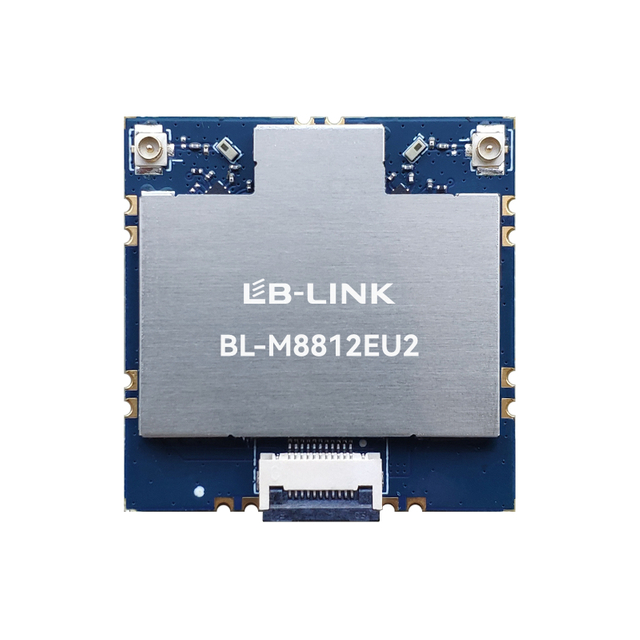
Selecting a high-power wireless module is not simply a matter of choosing the highest transmit-power figure on a datasheet. In industrial, security, UAV, robotics, and outdoor monitoring systems, link reliability depends on the whole RF path: receive sensitivity, antenna design, channel conditions, bandwidth, interference sources, host integration, and local radio rules. A module with strong anti-interference capability should help the final device maintain a usable connection when the environment is noisy, crowded, obstructed, or constantly changing. This guide explains how engineering teams can make that choice with clear, application-led criteria.
Key Takeaways
Assess transmit power and receive sensitivity together; either one alone gives an incomplete view of link performance.
Select the frequency band and channel width for the actual environment, not only for the headline data rate.
Look for RF filtering, a suitable front-end design, antenna flexibility, and tested coexistence behavior.
Validate the full system with its enclosure, antenna, cables, power supply, and real interference sources.
Choose a high-power wireless module manufacturer that can provide relevant technical documentation and integration support.
Start With the Link Requirement, Not the Module Name
A high-power wireless module is appropriate when a device must overcome meaningful path loss, maintain a connection over a longer distance, or deliver stable throughput in a challenging RF environment. Those needs appear in very different products. An IP camera may need a dependable high-definition video link across a warehouse yard. A drone or mobile robot may need low-latency video and control while moving. A factory gateway may need to operate around motors, drives, switching power supplies, and dense Wi-Fi traffic.
Before comparing modules, define what failure means for the application. A short telemetry delay may be acceptable for a non-critical sensor, while a video-control system may need a steady, low-latency connection. The engineering team should document the intended operating distance, obstacles, required throughput, acceptable latency, node density, power budget, antenna position, host interface, and expected temperature range.
This first step prevents a common selection error: buying high RF output power for a problem that is actually caused by poor antenna placement, an unsuitable frequency band, excessive channel width, receiver desensitization, or an overloaded access point. More transmit power can improve a link budget, but it cannot correct every source of packet loss.
For product teams developing embedded connectivity, the LB-LINK Wi-Fi module portfolio provides a useful starting point for comparing module families by wireless generation, interface, and intended application.
Evaluate Transmit Power and Receive Sensitivity Together
Transmit power describes how strongly a module can send a signal. Receive sensitivity describes how weak a signal the receiver can still decode at a defined data rate, modulation, bandwidth, and packet-error condition. Reliable long-range communication requires both.
A basic RF link budget can be expressed as:
Received signal level = transmit power + transmit antenna gain + receive antenna gain − path loss − system losses
System losses may include cable loss, connector loss, enclosure effects, polarization mismatch, and attenuation from walls, vegetation, machinery, or weather. In a real deployment, the received signal must remain sufficiently above the receiver’s noise floor and any local interference for the selected modulation and data rate.
That is why a single “high-power” label is not enough. Two modules can have similar transmit power but behave differently at the edge of coverage if their receive sensitivity, RF filtering, channel bandwidth, antenna layout, or driver behavior differs. Specifications also need context. Sensitivity measured at a low data rate is not directly comparable with sensitivity measured at a higher modulation and wider channel.
A practical comparison should ask:
Selection criterion
What to examine
Why it matters
Transmit power
Maximum power, power-control range, and applicable band
Supports the outbound portion of the RF link and affects thermal and regulatory design.
Receive sensitivity
Sensitivity at the relevant channel width and data rate
Determines whether weak return signals can still be decoded reliably.
RF front end
FEM, filters, low-noise receive path, and layout guidance
Helps manage noise, adjacent-channel energy, and system-level losses.
Antenna options
Connector type, number of RF chains, and approved antenna guidance
Gives the designer flexibility to optimize placement, gain, and polarization.
Channel bandwidth
Available narrowband and standard-bandwidth modes
A narrower channel can improve robustness when throughput requirements permit it.
Thermal behavior
Supply requirements, heat dissipation, and operating conditions
Sustained RF output can change thermal conditions and performance.
For example, the published HP-H09-01 high-power Wi-Fi module information identifies a built-in front-end module, up to 29 dBm transmit power, and -95 dBm receive sensitivity. It also supports 10 MHz narrow-bandwidth operation. These are relevant characteristics for long-distance video, monitoring, and industrial links, but the final design should still validate the complete radio path and compliance limits.
Treat Anti-Interference as a System Capability
Strong anti-interference capability is not one component or one software setting. It is the result of several choices working together.
At the module level, RF filters help reduce unwanted energy outside the desired channel. A well-designed receiver path helps the device distinguish a weak wanted signal from noise and nearby transmitters. A high-quality power design and grounded PCB layout reduce the risk that noise generated inside the product degrades RF performance. Where Wi-Fi and Bluetooth operate in the same device, coexistence design helps prevent one radio from unnecessarily disrupting the other.
At the network level, channel planning matters. A crowded 2.4 GHz environment may contain many Wi-Fi, Bluetooth, and non-Wi-Fi sources. In some applications, a suitable 5 GHz channel can provide more room for cleaner operation, though higher frequencies can experience greater path loss and may be less effective through dense obstacles. The appropriate choice depends on the site survey, regulations, antenna placement, and required range.
At the product level, the antenna is often decisive. A radio module installed next to a metal chassis, display cable, motor controller, or switching supply may perform much differently than it did on an evaluation board. Keep antenna clearances, ground-plane requirements, feed-line routing, and enclosure materials aligned with the module vendor’s guidance. If the application permits an external antenna, a connector-based design can allow better antenna placement and simplify field tuning.
The BL-M8812EU5 module, for instance, combines a high-power front end, RF filters, 2T2R capability, and support for 10 MHz narrow channels. Its published application focus includes long-range wireless video links such as IP cameras and UAVs. That combination illustrates why interference resistance should be assessed through the RF architecture rather than by power output alone.
Choose Frequency Band and Bandwidth for the Deployment
Frequency selection is a trade-off among coverage, congestion, throughput, antenna size, and regional regulations.
The 2.4 GHz band can be useful when a link needs practical propagation through ordinary indoor obstacles or when the target ecosystem is built around 2.4 GHz connectivity. However, it is commonly shared by many consumer and industrial devices. A system using this band should be planned carefully, especially in facilities with numerous access points, Bluetooth devices, wireless cameras, or legacy equipment.
The 5 GHz band can offer access to more channels and can be a strong choice for high-throughput video, industrial data, and point-to-point links where the path is reasonably clear. It is not automatically the best answer for every long-distance deployment; antenna choice, line of sight, channel availability, and local regulatory requirements still apply.
Channel width should also be chosen deliberately. Wider channels can support higher data rates but may expose the receiver to more noise and may be harder to sustain in congested spectrum. When an application sends control data, compressed telemetry, or video that can operate at a lower throughput, a narrower channel may provide a more robust operating point. The right setting is therefore the narrowest bandwidth that consistently meets the application’s data and latency needs.
The BL-M1105XS2 high-power wireless module is one example of a 5 GHz design that supports 5 MHz and 10 MHz narrowband modes with 2T2R operation and external antenna connectors. For a long-range design, such operating modes should be evaluated alongside the total data requirement rather than treated as a universal setting.
Match the RF Architecture to the Data and Motion Profile
A static environmental sensor, an IP camera, and a fast-moving UAV place different demands on a wireless link.
A low-data-rate monitoring device may prioritize dependable delivery, receiver sensitivity, low power consumption, and environmental tolerance. A security camera may prioritize sustained throughput, long-range coverage, and stable video under intermittent obstructions. A robotics or UAV system may additionally require rapid recovery from changing signal conditions, practical antenna diversity, low latency, and resistance to reflections caused by movement around metal structures or terrain.
Multiple RF chains can be valuable when the implementation supports diversity or MIMO appropriately. Diversity can improve reliability in multipath environments, where reflected signals may create fading at a particular antenna position. MIMO can improve throughput or robustness when the radio conditions, antenna separation, host design, and access-point capability support it. It should not be assumed that a higher chain count automatically guarantees better field performance; the antenna system and mechanical layout must support the intended radio behavior.
Application-specific guidance is often more useful than generic specifications. LB-LINK’s wireless connectivity solutions identify high-power 5 GHz, high-sensitivity modules for smart security, UAV, FPV, and robotics scenarios where long-range video transmission and interference resistance are central concerns. That context helps teams connect module attributes to a real product requirement.
Consider the Host Interface, Supply, and Mechanical Design Early
RF performance is only one part of module integration. The selected interface must match the host processor, operating system, throughput target, and available driver support. USB can be convenient for many compact platforms, while SDIO, PCIe, or M.2 interfaces may be more appropriate for other embedded architectures. Interface selection can affect throughput, board routing, mechanical design, and integration effort.
Power delivery deserves equal attention. High-power transmission can create short-duration current demand and heat. A weak supply rail, poor decoupling arrangement, or inadequate thermal path may cause unstable behavior that looks like an RF issue. Evaluate the module’s supply requirements under expected traffic, not only at idle. If the final device will operate in an enclosure outdoors or near heat-generating equipment, test it at the actual ambient temperatures and installation orientation.
Mechanical constraints can also affect an otherwise strong design. Compact devices may place antennas too close to batteries, displays, metal shields, or cables. In those cases, it may be better to choose a module with external antenna support, alter the enclosure, or use a different antenna topology than to compensate with more transmit power.
What to Expect From a High-Power Wireless Module Manufacturer
A capable high-power wireless module manufacturer should support selection with evidence that is useful to the engineering team. That includes clear datasheets, pin definitions, operating conditions, interface information, antenna requirements, reference designs, driver availability, and application guidance. When the product is intended for regulated markets, teams should also confirm what certifications, test reports, or integration restrictions apply to the exact model and antenna configuration.
The manufacturer should be able to discuss the practical difference between a requirement for range, a requirement for throughput, and a requirement for interference tolerance. These are related but not interchangeable. A supplier that asks about the link distance, obstructions, traffic pattern, band preference, host platform, antenna position, and target market is more likely to help identify a suitable solution.
For industrial hosts exposed to temperature variation and electromagnetic activity, LB-LINK’s industrial-grade Wi-Fi module solution shows how module selection can also consider environmental operating conditions, dual-band operation, platform compatibility, and integration format. Shenzhen Bilian Electronic Co., Ltd. can therefore be evaluated not only on a module’s specification sheet, but also on the relevance of its documentation and solution support to the intended device.
Validate the Candidate in the Real Installation
Bench testing is necessary, but it is not the final answer. A reliable validation plan should reproduce the conditions that make the application difficult: expected distance, representative walls or obstructions, active nearby networks, operating machinery, host traffic load, temperature range, and device movement.
Test throughput, packet behavior, reconnection time, latency variation, and video quality where relevant. Repeat the test with the final enclosure and antenna placement. If performance changes significantly between the open-board prototype and the final product, investigate antenna detuning, supply noise, ground return paths, cable routing, and thermal behavior before changing the module.
It is also important to test both directions of the link. A device may transmit strongly enough to reach an access point while still failing to receive a weaker return signal. This asymmetry is especially relevant in long-range or mobile systems. The objective is not merely to prove that a connection can be established; it is to verify that it remains useful during realistic operating conditions.
Conclusion
The right high-power wireless module balances RF power with receiver sensitivity, antenna flexibility, filtering, bandwidth options, interface compatibility, and the needs of the final installation. Strong anti-interference capability comes from the complete radio system: a suitable band, sensible channel planning, robust hardware integration, and field validation under real noise and obstruction conditions.
For long-range video, industrial monitoring, UAV, robotics, and security applications, begin with a measurable link requirement and compare candidates at the operating mode you will actually use. LB-LINK offers high-power and industrial wireless options that can be assessed against those requirements, but the final choice should always be confirmed through application-specific RF, thermal, and compliance testing.
FAQs
What makes a high-power wireless module different from a standard module?
A high-power wireless module is typically designed to provide greater transmit capability and, in many cases, an RF front end suited to extended-range or demanding links. However, meaningful performance also depends on receive sensitivity, antenna design, bandwidth, noise conditions, and the complete system layout.
Does higher transmit power always provide better anti-interference performance?
No. Higher transmit power may improve the outbound link margin, but it does not remove nearby interference, improve receiver selectivity by itself, or correct poor antenna placement. Filtering, sensitivity, frequency planning, channel width, and a clean power/RF layout are also important.
Is 2.4 GHz or 5 GHz better for a high-power wireless module?
Neither band is universally better. A 2.4 GHz design may offer practical propagation through some obstacles but often faces more congestion. A 5 GHz design can offer more channel options and high throughput, but path loss and obstacle penetration must be evaluated for the site.
Why does receive sensitivity matter for long-range wireless links?
Communication is two-way. A module may send a strong signal but still have difficulty decoding a weak return transmission. Good receive sensitivity at the required bandwidth and data rate helps preserve link margin when the signal is attenuated or the noise floor rises.
Can a narrow channel improve wireless reliability?
It can, when the application does not require the throughput of a wider channel. A narrower channel may reduce the amount of noise received and can support a more robust link budget. The trade-off is lower available data capacity, so it should be validated against the actual traffic load.
How should I test a module’s strong anti-interference capability?
Test the complete device in representative conditions, including its final enclosure, antenna, supply, traffic load, nearby networks, and environmental noise sources. Measure usable throughput, latency, packet behavior, reconnection performance, and stability at the expected range rather than relying only on laboratory specifications.
Guangming District, Shenzhen, as a research and development and market service base, and equipped with more than 10,000m² automated production workshops and logistics warehousing centers.